- #JFET TRANSISTOR DIAGRAM HOW TO#
- #JFET TRANSISTOR DIAGRAM MANUAL#
- #JFET TRANSISTOR DIAGRAM PORTABLE#
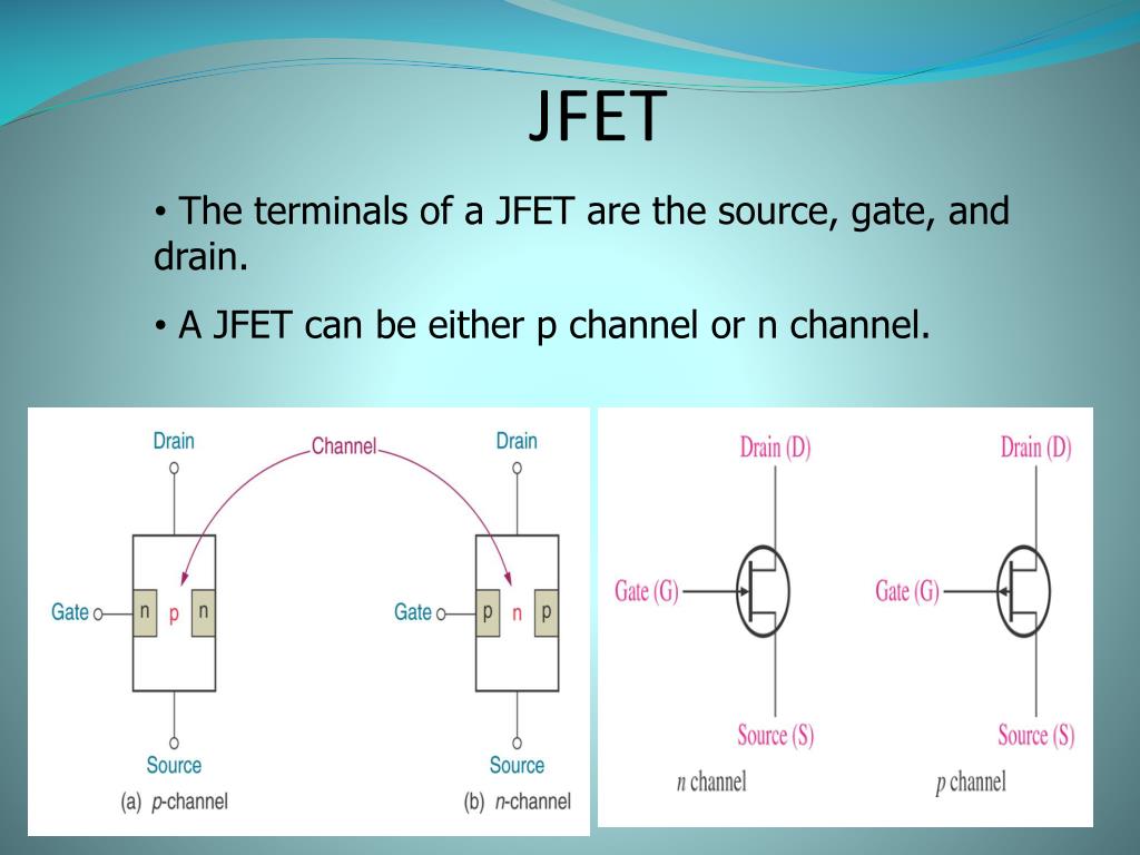
Ideal JFETs cannot be fabricated by themselves, in this model, the ideal JFET and the source resistor $r_s$ form an indivisible package. Transistor voltages and currents are labeled by subscripts referring to the appropriate lead. JFETs are drawn as shown to the right where the gate, drain and source (G, D, S, respectively) labels are normally omitted.


By convention, it is referenced to the source. Of course, the gate voltage needs to be referenced to some other potential.

Typical transistors have three leads in the case of a JFET, a voltage on one lead (called the gate) is used to control a current between two other leads (called the source and the drain). Transistors are amplifiers a small signal is used to control a larger signal. JFETs will give us a good picture of how transistor circuits work. Although MOSFETs are much more common than JFETs, we will work with JFETs because MOSFETs burn out so easily. Once soldered into a circuit, however, MOSFETs are quite robust. Static electricity easily destroys MOSFETs they can be burnt out simply by walking across a room on a dry day while carrying them in your hand. (To be complete, each type of FET is further subdivided into n and p-channel FETs, and, for MOSFETs, enhancement and depletion MOSFETs, but we won't cover this now.) FETs are subdivided into two major classes: junction field-effect transistors (JFETs) and metal-oxide-semiconductor field-effect transistors (MOSFETs). We will limit our study to FETs because their physical mechanism is simpler. The physical mechanisms underlying the operation of these two types of transistors are quite different. There are two principle types of transistors: bipolar transistors (BJTs), and field-effect transistors (FETs). Why does increasing a follower’s source resistor ( $R_S$) decrease its JFET’s transconductance? (Refer to the discussion in 4.16.) Why does this degrade the performance of a source follower? Why does it give the equilibrium current for the self-biased current source?Ĥ.
#JFET TRANSISTOR DIAGRAM HOW TO#
Explain how to use load line analysis as outlined in the background materials. In a few sentences, explain how a self-biased current source works.ģ. What is the maximum allowed gate current? What happens if this current is exceeded?Ģ.

#JFET TRANSISTOR DIAGRAM PORTABLE#
NOTE: You can check out and keep the portable breadboards, VB-106 or VB-108, from the 111-Lab for yourself ( Only one each please) Reprints and other information can be found on the Physics 111 Library Site. JFET Readingthis is a big file so download it.Ĭurve Tracer Information at bottom of page The Art of Electronics, Horowitz & Hill Chapter 3
#JFET TRANSISTOR DIAGRAM MANUAL#
Microelectronic Circuits 5th Solutions Manual Sedra & SmithĪrt of Electronics Student Manual,Hayes & Horowitz Chapter 3 Microelectronic Circuits, Sedra & Smith Chapter 5 © 2016 by the Regents of the University of California.


 0 kommentar(er)
